The Zener Diode – What it is, how it works and it’s history
What is a diode & how does it work?
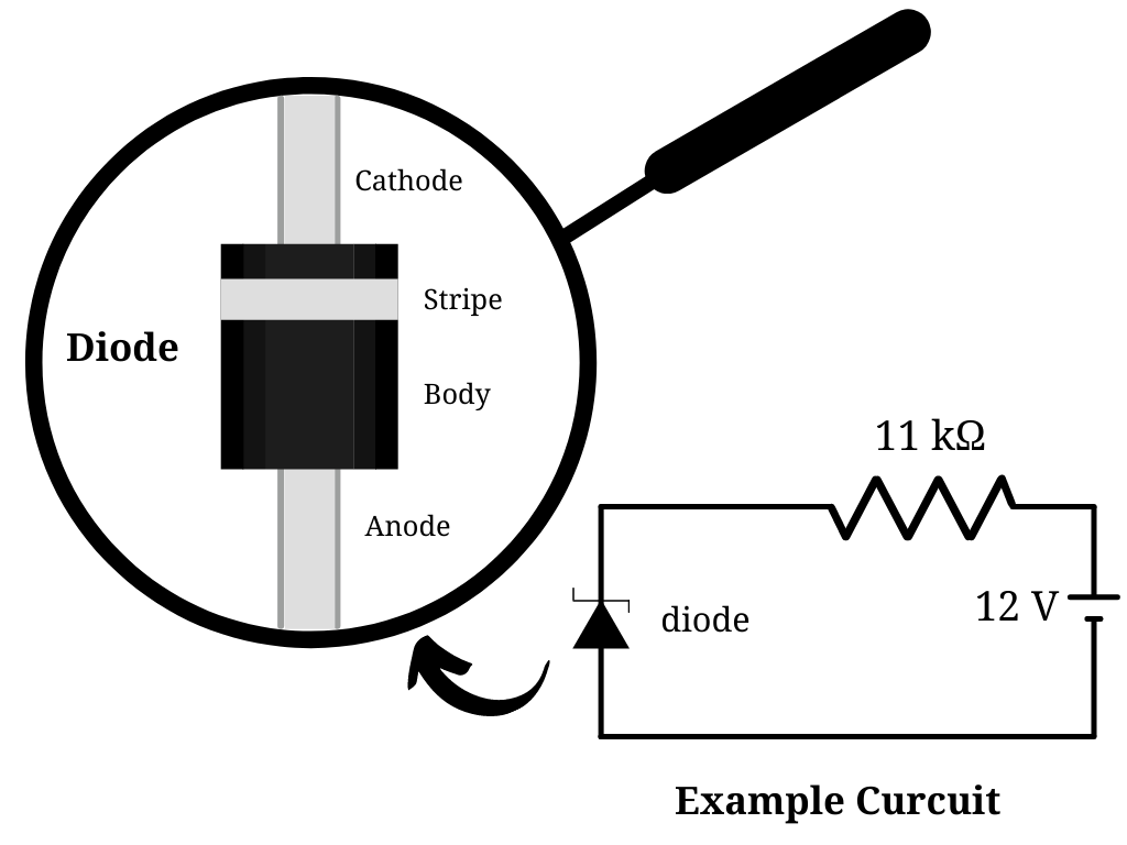
A diode is a circuit component that only enables current to flow in one direction. Diodes come in different sizes, and they typically have a black cylindrical body with two leads coming to the sides (Anode and Cathode) and a stripe at the Cathode end. Diodes are like one-way streets. The current can only move from the Cathode end to the Anode end through the diode. This occurs because the diode prevents current from flowing in the opposite direction from the Anode side. A diode is reverse biased when it acts as an insulator and forward biased when it allows current flow. A diode’s anode and cathode are its two terminals. Diodes are used in circuits to limit voltage and convert AC to DC. Semiconductors like silicon and germanium are employed to get the most out of diodes. Even though they both transfer power in the same direction, the way they do so is different. Diodes come in various shapes and sizes, each with its own set of applications, such as Zener diodes. Switches, signal modulators, signal mixers, rectifiers, signal limiters, voltage regulators, etc., are all examples of diode applications.
What makes a Zener diode different from a regular diode?
Zener diodes are one of the diodes used for particular purposes. Except for one key distinction, Zener diodes work just like conventional diodes. The reverse-breakdown voltage of Zener diodes is known as “Zener Voltage.” This means that Zener diodes can only stop current from flowing through a circuit up to a particular voltage. If the reverse-breakdown voltage of a Zener diode is 10 V and the current flow is only 5 V, the Zener diode will block the current flow. In another scenario, if the circuit’s current flow is 11 V, the Zener diode will allow the current to pass.
What is the point of a diode that conducts in both directions? you might wonder. A Zener diode comes in handy when creating voltage regulators, over-voltage protection circuits, and other circuits. It may be used to navigate partial current flow in a different direction in a circuit. The construction of Zener diodes also differs from the construction of regular diodes. These diodes are manufactured from severely doped N and P-type semiconductors, varying amounts of doping to achieve varying breakdown voltages. As a result, different voltage levels of Zener diodes have varied voltage capacities.
In summary, Zener diodes are designed to be used in reverse-bias mode, with a low, steady breakdown voltage, or Zener voltage. They begin to conduct significant reverse currents. A Zener diode can work as a voltage regulator by functioning as an auxiliary load, pulling more current from the source when the voltage is too high and less current when the voltage is too low.
The early history of the Zener diode
Clarence Melvin Zener was the one who initially described the benefits of this diode. Clarence Zener was a professor in the Department of Physics at Carnegie Mellon University. His research interests were in solid-state physics. He graduated from Stanford University in 1926 and obtained his doctorate from the same institution in 1929. In 1950, he invented the Zener Diode, which is now used in modern computer circuits. In 1934, Clarence Zener released a paper on the breakdown of an electrical insulator. He was known worldwide for pioneering a field of science called “internal friction,” which was the focus of most of his research.
How to protect your circuit from over-voltage damage with a Zener diode?
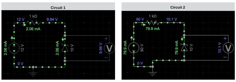
You may be experiencing unknown or mysterious failures in your projects when utilizing voltage-sensitive motors or other components in a circuit. Voltage-sensitive components can sometimes burn because simply they cannot handle the amount of voltage in the current. Let’s take a look at the circuit figures. Circuit 1 has a 12 Volt power supply with a reverse-biased Zener Diode. The Zener voltage is 10 Volt; therefore, the breakdown voltage has been exceeded by the 12 Volt power supply and doesn’t allow more than 10 Volts to the Voltmeter. If we increase the voltage of the power supply to 90 Volts as shown in the circuit 2 diagrams, then the Zener Diode will still allow the current to flow past it. However, the current that goes to the Voltmeter is still about 10 volts. Hence, the Zener diode can be used to create a voltage regulator using this logic in a circuit.
Attributes of Zener Diodes
Nominal voltage, power dissipation, forward drive current, forward voltage, packaging type, and maximum reverse current are attributes that are used to classify different Zener diodes. Let’s get to know some of these attributes.
Nominal Voltage
Zener Breakdown Voltage is also called the Nominal Operation Voltage. It is one of the important parameters for Zener Diode selection.
Power dissipation
The greatest amount of power that the Zener current can discharge is represented by this value. Exceeding this power rating causes the Zener diode to overheat, potentially damaging it and causing the failure of the components connected to it in a circuit. As a result, while choosing a diode for a specific application, this element should be considered.
Maximum Zener Current
At the Zener voltage, this is the maximum current that may be passed through the Zener diode without destroying it.
Minimum Zener Current
This is the minimum current required for the Zener diode to enter the breakdown area and begin working.
Other parameters that act as diode specifications must all be carefully studied before deciding on the type of Zener diode required for any particular design.
Shop Variable Resistors
Check out other articles from our Blog
Contact Us
Accepted Payments