17 March,2022
 By Aovxers
 AOVX hardware workshop
In Aovx's asset monitoring device, Triode are often used. In the previous discussion, the types and functions of Triode were also introduced.

As a logistics visualized supply chain management solution provider focusing on the field of wireless communication. Generally , in the Aovx asset monitoring device, the diode is the core component of the integrated circuit and can also amplify the signal.
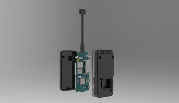
For example, Aovx's V-series, vehicle tracking devices are mainly used in fleet management business.
The Features included :
Motion Detect
Vibration Alert
Electronic Fence
Tamper Alert
Low Battery Alert
ACC ON OFF Detection
GPIOs
But the features function design can not do without Triode , if you have more interested in this ...Lets learn the Common circuit design of diodes immediately
Triode differential amplifier circuit
The differential amplifier circuit rarely appears alone in circuit design, and it is generally used as the input stage of the Op amplifier (operational amplifier). Therefore, the focus of our discussion is also on its characteristics.

Figure 22-1
The differential amplifier circuit shown in Figure 22-1 is the combined form of two identical common-emitter amplifier circuits (Q1 and Q2 circuits). .
When no signal is input, the emitter currents of Q1 and Q2 are equal (V(be) and β of transistors Q1 and Q2 are exactly the same).
When there is a signal input, the amount of change of the emitter current of Q1 and Q2 is the same, but the direction of increase and decrease is different, but the sum of the emitter current is still certain.
We take the single-ended input method of "Vin1 inputs a signal with an amplitude of A, and Vin2 is grounded" as an example for discussion, as shown in Figure 22-2.
①When Vin1 inputs a signal with an amplitude of A, the V(be) of Q1 is larger than the V(be) of Q2, so that the emitter current of Q1 generates an increment of △l, which is determined by the voltages of Q1 and Q2. If the emitter current and the current source control remain unchanged at 2Le, then the emitter current of Q2 will inevitably produce a decrement of Δl. By default, the emitter current is approximately equal to the collector current. In this way, the increase in the emitter current of the Q1 tube will lead to an increase in the voltage drop on R3, which will lead to a drop in the potential of the collector output vc1, that is, the change of vc1 and the change direction of the input waveform of Vin1 on the contrary. Similarly, Q2
The reduction of the tube emitter current will cause the voltage drop on R4 to decrease, which will lead to an increase in the potential of the collector output vc2, that is, the change of vc2 is in the same direction as the change of the input waveform of Vin1.
Then, the polarities of vc1 and vc2 are opposite, vc1-vc2 = 2vc1 = 2vc2 = Au(Vin1-Vin2).
There is a key thing here, that is, when the signal amplitude A is added to the Vin1 terminal, if the traditional common-emitter amplifier circuit is used, the potential on the emitter will also change in the same direction as A. But in the differential amplifier circuit, the potential Ve on the emitter has only the variation range of A/2. Why is this? It can be understood that the Vin1 signal passes through V(be1), V(be2) to the ground of the Vin2 terminal, and divides the amplitude A. In this way, if the voltage gain of the differential amplifier is Au, then the gain of the voltage amplitude of vc1 and vc2 to ground (single-ended output gain) is Au/2; the difference gain between vc1 and vc2 is Au.
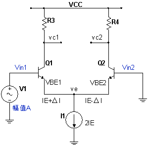
Figure 22-2
② If Vin2 inputs a signal with amplitude A and Vin1 is grounded, the analysis method is the same as the above case; if both Vin1 and Vin2 input a signal with amplitude A at the same time, we know that this is a common mode input , according to the above analysis, it can be obtained that vc1=vc2=0, that is, there is no output at the output end, which is the so-called common mode rejection.
Since the emitter-to-ground AC resistance of the two common-emitter amplifier circuits composed of Q1 and Q2 is very small, the gain of the differential amplifier is about the value of the current gain coefficient β. Three resistors R(E1)=R(E2)=R(E) and R1 are added in Figure 22-3. The resistor R(E) is used to control the voltage gain, Au=Rc/Re .(Rc=R3=R4 )
②The resistor replaces the current source circuit and controls the current at Ve/R1 when the voltage amplitude of the input signal does not change very much (that is, when the Ve voltage does not change much). Generally, a mirror current source or a common emitter circuit is used as the current source.

Figure 22-3
In addition to hardware knowledge sharing, there are other series of products in Aovx, such as: goods monitoring, assets tracking, vehicle tracking, environment monitoring. It can meet the different needs of customers in many industries and avoid asset damage.

Aovx's products mainly include 4 series. "GAVE"

By showcasing the diverse solutions of these four series of products, we have gained more than 3,000 followers on LinkedIn.
Want to learn more about Aovx solutions?
Please follow our company page :
https://www.linkedin.com/company/aovxassetstracker/posts/?feedView=all&viewAsMember=true


Latest Posts
Categories