 03 December,2021
 By AOVX
 AOVX hardware workshop
At the beginning of the establishment of AOVX, the founder was responsible for the research and development, testing, and marketing of the equipment.
In order to save costs, in the process of testing the equipment, the founder chose to make his own power supply equipment.
After unremitting efforts, the scale of AOVX has finally expanded. Today, hardware engineers will share how to convert alternating current into direct current, learn how to make a self-made power supply, and help small companies reduce the cost of starting a business.

A low-cost AC-DC conversion circuit
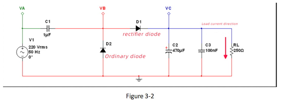
As shown in Figure 3-2, 220VAC is divided by capacitor C1 to provide DC power to load RL. V1 is an AC power source with an effective value of 220V, and the AC frequency is 50Hz. The diode D1 is used to prevent the current from flowing in the reverse direction (V1→RL→C1→V1). With D1, the current flowing into the load RL is DC, and the direction of the current flows from top to bottom, so D1 is also a rectifier. The function of the ordinary diode D2 is to discharge C1. If there is no D2, when V1 is in the positive half cycle, it is actually the first half of the positive half cycle. After C1 is fully charged, the capacitor C1 can no longer be charged later. And the capacitor C1 itself has no way to discharge, which means that V1 cannot provide energy to the load through C1.
We mentioned in Skill 1 that the current of the capacitor leads the voltage by 90° phase. In the left figure of Fig. 3-3, the relationship between the voltage and current waveforms of the capacitor also reflects this result. Let us look at the part between the two red dashed lines in the figure, which shows that during the period between the first half of the positive half cycle and the second half of the negative half cycle, V1 provides energy to the load through C1.
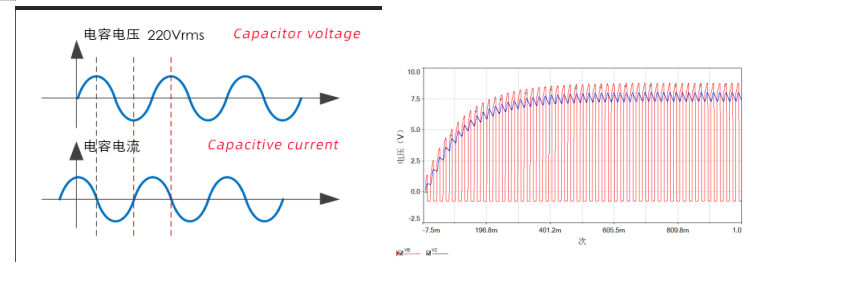
Figure 3-3
Now the question is, how much current can this power supply circuit provide to the load?
First of all, we can get from the left diagram of Figure 3-3 that in each cycle of V1 AC voltage input, only half of the cycle time provides energy (or current) to the load, so this is half-wave rectification. 1uF capacitor C1 has a capacitive reactance of V1 with a frequency of 50Hz.
Therefore, this power supply is equivalent to a current source, and the capacitive reactance of the capacitor is equivalent to the internal resistance of the current source, and the current provided to the load is. (Note: Since it is half-wave rectification, the average output voltage should be 0.45×220V, skill 2)
The waveform on the right of Figure 3-3 shows the voltage waveforms of the VB (red) and VC (blue) test points in Figure 3-2. The voltage of VC is also the voltage of load RL, and the waveform is stable at about 7.5V. This 7.5V voltage value is exactly the voltage formed by the current 30mA output by the current source that we calculated, flowing through a 250Ω load. You can also use the Multisim tool to simulate, you can change the load resistance value RL to 500Ω to see if the voltage is 15V; then change the load resistance value RL to 2KΩ to see if the voltage is 60V.
In this way, we can adjust the capacitance value of the capacitor C1 according to the required load current during the design, so that different output currents can be obtained. This kind of conversion circuit does not need to use a transformer to convert high AC voltage into DC power supply, which achieves the advantage of low cost, but the disadvantage is that the current provided is relatively small. Generally, it is used when the load current is less than 100mA. Therefore, the output provides The current should not exceed 100mA.
We usually use voltage sources, and we also hope to have a stable output voltage to supply power to the load. Instead of the current source circuit like Figure 3-2, the output voltage varies with the load. As shown in Figure 3-4, we changed the ordinary diode D2 to a Zener diode on the basis of Figure 3-2. One function of this Zener tube is to stabilize the output voltage, and the second function is to provide a discharge path for the capacitor C1. Due to the presence of the 13V voltage regulator tube D2 in the figure, the output DC voltage is stabilized at about 12V.
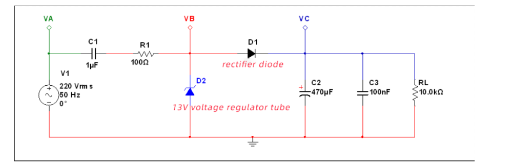
Figure 3-4
Generally, a small resistor R1 is made at the front end of the voltage regulator tube, in order to protect the voltage regulator tube, it will not damage the voltage regulator tube when the load is open. Need to explain here, the power output is still 30mA current, but it needs to allocate 5mA current to the Zener tube for voltage stabilization, and the remaining 25mA is provided to the load.
The load in Figure 3-4 is 10KΩ. Since the output voltage is stable at 12V, the current flowing into the load is. Then some current flows into the voltage regulator tube. Therefore, the power parameters of the regulator should be paid attention to, especially when the load is disconnected, the current will all flow to the regulator tube, so whether the power of the regulator tube can be satisfied, such as the power parameter of the regulator tube selected in this figure Need to be greater than.
Figure 3-5 shows the voltage waveforms of the VA, VB, and VC test points of the circuit in Figure 3-4. The figure on the left highlights the 220VAC input voltage waveform at the VA point, and it can be seen that its peak value is about 311V. The right figure highlights the voltage waveforms at points VB and VC. VB is the red pulsating voltage waveform, and VC is the blue filtered voltage waveform. After about 180ms, the output voltage stabilizes at about 12V.
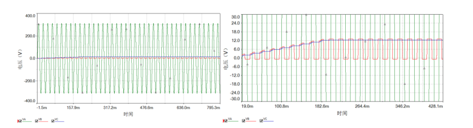
Figure 3-5
In addition, the non-polar capacitor C1 is connected to a live wire, with a withstand voltage of at least 400V (the maximum value of 220V alternating current is 310V). It is better to connect a large resistor in parallel to the capacitor C1. When there is no AC input and no load, it can provide a discharge path for the capacitor C1, so as not to be touched by human hands.
If you mastered the above methods, you can save more budget at the began.
After we completed it and save the cost for developing new products, what did we have done?

Check our business here:https://www.aovx.com/products.html


Latest Posts
Categories


