 10 December,2021
 By AOVX
 AOVX hardware workshop
In recent years, with the popularization of vehicles, financial leasing loan vehicles, fleet management, and vehicle anti-theft will all use vehicle monitoring terminals to gradually enter the public's field of vision.
After using the vehicle monitoring equipment, the manager can know the location of the vehicle, the status of the vehicle in real time, and realize remote dispatching. In the course of use, managers often cannot continue to work due to insufficient power of the vehicle monitoring equipment, which affects the efficiency of management.
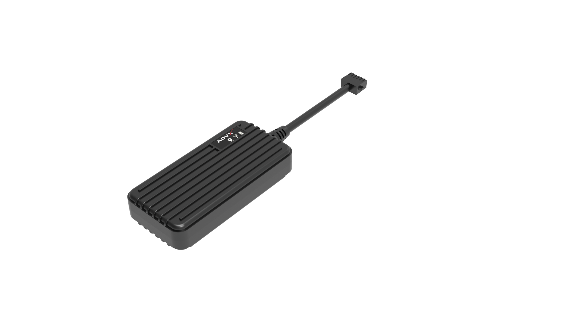
AOVX's vehicle monitoring equipment uses external direct current, which is processed and used by our equipment hardware, thus avoiding the trouble of equipment power failure. Engineers mainly used the principle of linear step-down circuit in optimizing the power supply capacity of the equipment. Common linear step-down circuits include fixed output type and adjustable output type with feedback.
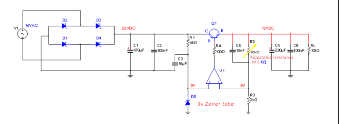
Use a current-limiting resistor and a 12V voltage regulator tube to achieve a 12V DC voltage output. As shown in Figure 4-1, the voltage drop on the current-limiting resistor R1 is, assuming that the regulator tube can stabilize 12V, the required regulated current is 5mA. If R1=2.2KΩ, it can provide the current of the voltage regulator tube 12V, that is U(R1)/2.2KΩ=5mA,Note that the current supplied to the load is not considered here. Now we add the load RL=10KΩ, it grabs the current with the regulator tube, so that the regulator tube cannot obtain the 5mA regulated current necessary for 12V regulated output, then the value of the current limiting resistor R1 needs to be reduced to ensure While the voltage regulator tube stabilizes the current, it can also provide load current.
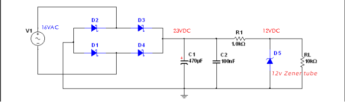
Now we modify the current-limiting resistance R1=1KΩ, so that some current, 5mA is used for voltage stabilization, and the maximum 6mA can be provided to the load.
With this combined linear step-down method, the load current is limited to the maximum, and the current provided to the load cannot be too large. If it is too large, on the one hand, the thermal power consumed by the resistor on R1 will become very large, resulting in low efficiency. On the other hand, when there is no load, all the current will flow into the zener tube, as calculated above, the total current of 11mA will flow into the zener tube. Multiplying with the regulated value of 12V is the power to withstand, so when choosing a stable It is necessary to pay attention to the maximum power value when pressing the tube device. That is, the power of the Zener tube D5 is greater than that, if the load current is larger, you need to choose a higher power Zener tube device
Since the power supply mode of resistance + voltage regulator tube is not suitable for large current, we first introduce a small load current into the base L(b ) of the transistor, so that an amplified current L(c)= B*L (b)
will be generated on the collector-emitter of the transistor, and then this The collector current L(c)
is provided to the load as an output current.
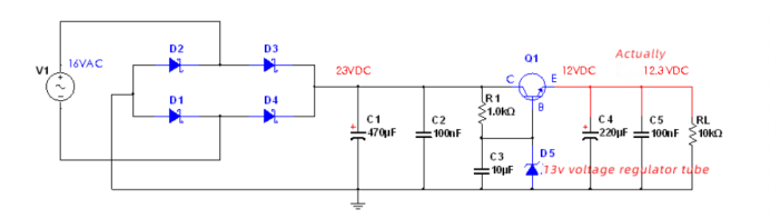
4-2
In Figure 4-2, the current-limiting resistor R1 and Zener tube D5 provide 13V voltage regulation. The load current provided by this combination of R1+D5 is the base current of the transistor. This current is very small, so there is no voltage on R1. There will be a lot of consumption. The choice of the 13V regulator tube is to take into account the voltage drop of the transistor VBE, so the output voltage of the emitter of the transistor Q1 is 12.3V. The output voltage of this step-down method is different from the voltage regulator of the regulator tube by one emitter junction voltage drop. .
Use a transistor to introduce feedback voltage regulation
Because in the above two fixed voltage combination methods, the output voltage depends on the voltage regulation value of the voltage regulator tube, and the accuracy of the voltage output is relatively poor. Therefore, we introduce negative feedback to better stabilize the output, while also achieving adjustable output voltage.
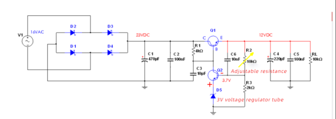
5-1
In Figure 5-1, the sampled value after dividing the output voltage through resistors R2 (adjustable resistor) and R3, based on the relationship between the base and emitter of the transistor Q2, forms an error comparison with the 3V voltage of the Zener tube , The error value will cause the change of the base current of Q2 (the relationship between Ube and Ib), which will cause the change of the collector current of Q2, and finally affect the base current of the transistor Q1, and then affect the current change of the collector of Q1 , Finally cause the stability of the output voltage of Q1 to change.
The base voltage of Q2 is V (b) =V (a) *R(3) / (R (2) +R (3) ) ,Which represents the output voltage, which is 12VDC in this figure.
Figure 5-2 shows the error amplifier composed of the common-emitter amplifier circuit of the triode. On the whole, it is a negative feedback circuit. We can regard the emitter and base of the triode as the same direction input and reverse input of the OP amplifier. The potential of the two positive and negative input terminals must satisfy this relationship: V (f)=V(z) +U(be ), (Rather than the virtual short characteristic of the real OP amplifier, that is, the potentials of the two input terminals are equal). In this way, the output of the power supply reaches the following balanced formula:
V(a) =V(f) * (R(2) +R (3)) /R (3).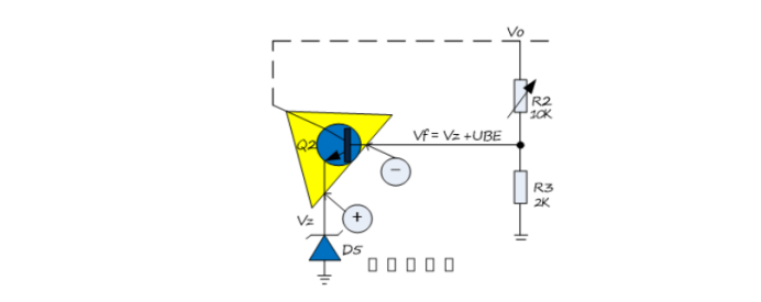
5-2
This circuit, in addition to feedback and stable output voltage, we can also obtain different voltage output by adjusting the variable resistor R2. It is worth noting that if the resistance of this resistor is too large, it will affect the base current of the Q2 tube, thereby affecting the supply of the voltage regulator current; too small will make the voltage divider resistor fearless loss of current, we generally take a few KΩ ~ Variable resistance of tens of KΩ. Resistor R3 also needs attention. According to the output voltage balance expression above, R3 cannot be too large, too large will affect the maximum output; otherwise, too small will affect the minimum output.
Due to the temperature characteristics of the PN junction of the triode:
Every time the temperature rises by 1°C, the Ube voltage of the triode will drop by 2 to 2.5mV.
At 25°C at room temperature, for every 60mV increase in the base voltage, the collector current increases by 10 times.
Therefore, the triode Q2 in Figure 5-1 may affect the output at a certain temperature, that is, the temperature drift is very large. Therefore, replacing the triode with an op amp with low temperature drift can better stabilize the output voltage.
5-3
As shown in Figure 5-3, when the output voltage of 12VDC changes, the voltage at the reverse input terminal of the op amp circuit will have a change greater than or less than 3V. At this time, the op amp will adjust the output accordingly to control the transistor. The base current of Q1 has achieved the purpose of stabilizing the output voltage.
The op amp needs to have a certain current output. If the load current is large, then the output of the op amp can not directly drive the base of Q1, but a triode, and the collector current of this triode is used to drive the base of Q1.
If you want to learn more about the hardware knowledge of vehicle monitoring device, please follow our website : www.aovx.com , or send an email directly to info@aovx.com, our technicians will help you as soon as possible.


Latest Posts
Categories


