 17 December,2021
 By AOVX
 AOVX hardware workshop
Whether it is vehicle monitoring or asset and cargo monitoring, it belongs to the scene of low voltage supply. Therefore, in the process of developing AOVX monitoring equipment, we first need to learn the use and analysis of LDO (linear low-dropout output power supply).
Basically all linear regulators use the principle of negative feedback to stabilize the output voltage. As shown in Figure 7-1, this is an LDO feedback network. The output voltage Vo is sampled by a voltage divider and fed back to one input of the error amplifier, and is compared with another input terminal connected to the reference voltage source Vref. The result of the comparison is controlled by the output current of the regulator tube to maintain the stability of the output voltage Vo .
the key point is How does LDO achieve Vo stability?
The stability of the system, from the point of view of the transfer function, to put it bluntly, is to stabilize the LDO system by adjusting the position of the zero poles. Let's explain in detail below.
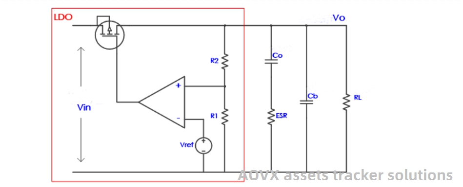
Figure 7-1
Let's first look at what exactly the zeros and poles affect in the system, as shown in Figure 7-2.
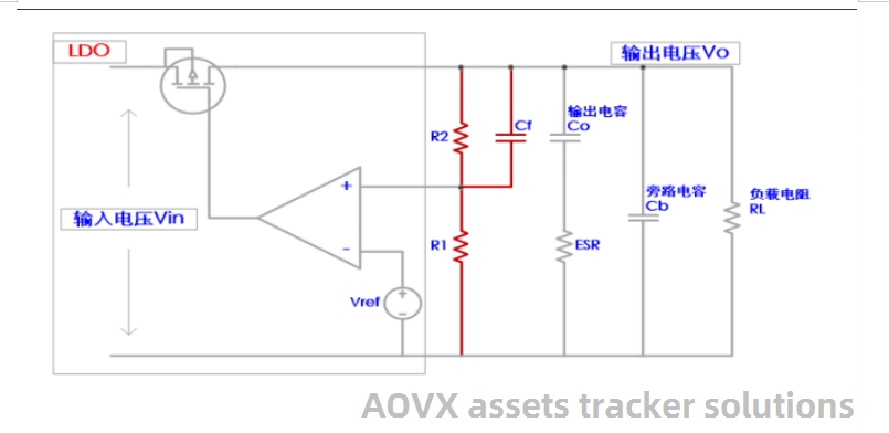
Figure 7-2
On the Bode plot, every time a pole is added, the slope of the gain curve will change by -20dB/decade, that is, the gain will decrease as the frequency increases. At the same time, the pole also affects the phase shift. As the frequency increases, the phase shift gradually increases from 0° to -90°, and the phase shift at the pole is -45°. A pole increases the phase shift of -90° at most, so it is unconditionally stable in a single-pole system, such as a pure RC (resistance-capacitance) circuit system. However, if the unity gain bandwidth is a system with more than two poles, as the frequency increases, a phase shift of -180° will occur and cause oscillation. So we have to find a way to overcome or offset the impact of multiple poles.
On the contrary, every time a zero point is added, the slope of the gain curve will change +20dB/decade, that is, the gain will increase as the frequency increases. At the same time, the zero point also affects the phase shift. As the frequency increases, the phase shift gradually increases from 0° to +90°, and the phase shift at the zero point is +45°. We can see that the effect of the zero point on the gain and phase is opposite to that of the pole, so the zero point can be used to offset the effect of the pole on the gain and phase shift. To put it bluntly, loop compensation is to add appropriate zeros to compensate or offset the outer poles in the system.
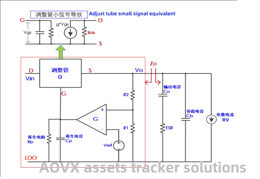
Figure 7-3
From the figure, we can get the expression of output impedance Zo as:
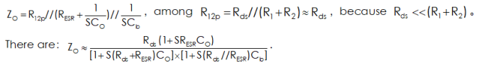
Respectively make the denominator and numerator of the above formula equal to 0, then the pole and zero expressions of the transfer function can be obtained:

At this point, let's discuss it first. Since there are two poles and a zero on it, when the zero offsets one of the poles, it is a single-pole system, which should be unconditionally stable. In fact, there is a third pole in the closed loop. This pole is generated by the parasitic capacitance Cp of the MOS tube and the output impedance Rp of the amplifier. The third pole is obtained.
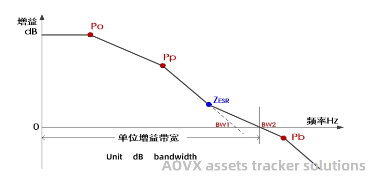
Figure 7-4
Figure 7-4 shows the conditions of the poles and zeros of the gain curve of the LDO system (Equation 7-1). I can see that in the unity gain bandwidth BW2, the zero point generated by the ESR of the output capacitor compensates for the double pole, so that when the gain reaches 0dB, the phase shift must be less than -180°, so that the system is stable.
At this time, the double poles produce a phase shift of -180°, which causes the system to be unstable. So the choice of the ESR of the output capacitor is very important, it can be used to improve the stability of the LDO, please don't ignore it.
However, what is the right ESR? Because ESR is too large or too small will bring the system into an unstable environment.
Figure 7-5 describes that ESR is too small or too large will cause the unity gain bandwidth, after zero compensation, there are still more than 2 poles, at 0dB gain, there is a -180° phase shift, which makes the system unstable. . Therefore, some LDO specifications mention the value range of ESR.
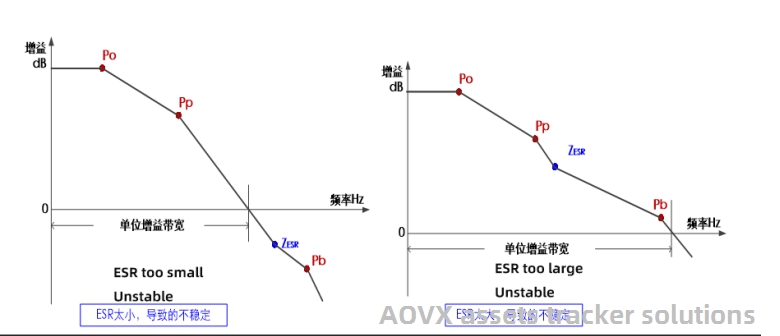
Figure 7-5
Of course, there are also many LDO specifications that suggest using capacitors with low ESR, such as ceramic capacitors. This is because zero points have been added to the LDO for compensation.
In addition, in addition to the zero point produced by the ESR of the output capacitor for compensation, there is also a compensation called "feedforward compensation method".
As shown in Figure 7-6, we can often see that a small capacitor Cf is connected in parallel with the upper resistor of the voltage divider, generally at the pF level. This capacitor is called a feedforward capacitor.
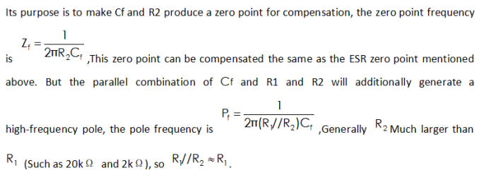
In this way, the zero point and the pole are far apart. On the one hand, the compensation of the zero point greatly improves the phase margin, and on the other hand, the high-frequency pole is kept outside the unity gain bandwidth to make the system stable.
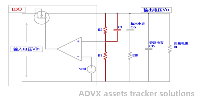
Figure 7-6
Based on the above content, you can master how to adjust the external voltage to ensure the smooth operation of the equipment in the scene of low voltage.

AOVX tracker solutions is a logistics visualized supply chain management solution provider focusing on the field of wireless communication.for more details : please check our website : www.aovx.com


Latest Posts
Categories


