 06 January,2022
 By AOVX
 AOVX hardware workshop
Why the capacitors analysis is very important in the tracker research and development ?
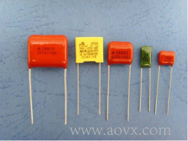
Last week, we have learned the Capacitor definition and functions, in the tracking device the capacitor.
Learn more details via : https://www.aovx.com/News_information/203.html

This week we need to analyze how to learn the capacitor working principle.
Why this is important?
As a logistics visualized supply chain management solution provider focusing on the field of wireless communication.We utilize the capacitor principle to help the tracker function remains stable.
How to analyze capacitor ?
Figure 10-2 illustrates the charging and discharging process of the capacitor, which is also the process of storing and releasing charge.
When the switch S is on the left, the power supply U releases the charge to the capacitor C, and the rate of release is, that is, the amount of change in the charge per unit time forms a current. At the beginning, there is no charge on the capacitor C, so the voltage applied to the capacitor by the power supply is the largest, and the charging current is also very large at this time.
Therefore, in the use or design of some power supplies, although a large number of capacitors can be added to the output terminal to get a good filtering effect, the instantaneous large current required when charging a large capacitance requires consideration whether the output of the power supply can withstand this High Current.
When the switch S is on the right, the capacitor C discharges to the load, and the LED lights up through the resistor R. As the charge on the capacitor C is released to the point where the voltage and current to provide the load are not available, the LED goes out. Of course, the larger the capacitance value of the capacitor C, the more stored electric charge will be, and the duration of the LED lighting will be longer.
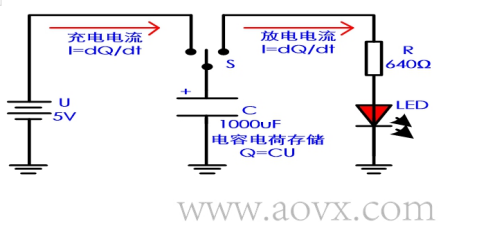
Figure 10-2
In any case, please memorize and understand the following formulas.
Memory formula 1:
Memory formula 2: charge:; discharge:
Memory formula 3: Store energy:
Memory formula 4: capacitive reactance:
The time that determines this charge and discharge is described as the RC time constant. As shown in Figure 10-3, here is a common little experience:
1. When the charge and discharge time reaches 5RC, we think that the capacitor is fully charged or discharged;
2. The time between the 10% and 90% rise or fall of the voltage across the capacitor on the charge and discharge curve (or the rising or falling edge of the waveform generated by the RC circuit) is about 2.2RC.
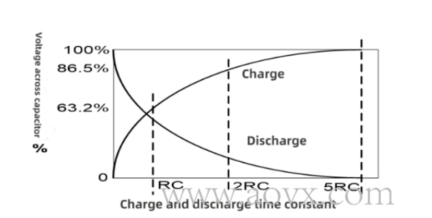
Figure 10-3
So, let's go back to the example in the figure above. When the switch S is on the left, the power supply U charges the capacitor C. The resistance R in the time constant RC is the small output resistance of the power supply U. If it is 1Ω, then the RC time is 1Ωx1000uF=1ms. In other words, the 5ms capacitor is fully charged. When the switch S is on the right to discharge, the RC is about 640ms. According to the characteristic voltage drop and drive current of the LED, the time that the LED can continue to light can also be calculated.
The above is the function of the capacitor's charging storage and discharge of electric charge, and the characteristics of the next through-pass are discussed below.
Capacitors’ DC-blocking characteristics are actually infinite impedance for DC signals, which is similar to an open circuit, while the impedance for AC signals of different frequencies is 1/2πfC.
The higher the frequency, the lower the impedance. Capacitors are generally used for functions such as DC blocking, bypassing and filtering. As shown in the figure below, the attenuation of the in-band signal is not considered.
The cut-off frequencies of the high-pass and low-pass filters are both :

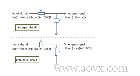
Figure 10-4
In Figure 10-4, the RC low-pass filter can be regarded as an integrator, and the RC high-pass filter can be regarded as a differentiator. The meaning of the integrator is to superimpose the input signal within a period of time to sum, and the meaning of the differentiator is to extract the rate of change of the input signal.
The integral expression is:
 (constant)
The differential expression is:

When designing the circuit, pay attention to the parasitic capacitance, which is an important part, especially at the pads of the crystal or oscillator that outputs the high-frequency clock. The larger parasitic capacitance will cause the clock to deform. Therefore, during the layout of the high-frequency clock crystal oscillator, the GND pad of the layer below the pad of the high-frequency signal will be dug out to reduce the influence of parasitic capacitance on the clock.
There is also a capacitor characteristic that is often talked about, that is, the voltage of the capacitor cannot change suddenly. When the current (charge) flows into the capacitor, the voltage across the capacitor can only gradually increase; when the current (charge) flows out of the capacitor, the voltage across the capacitor can only gradually decrease. But the electric current can carry on the burst operation.
In addition, the AC signal passed by the capacitor, the current of the AC signal will lead the voltage by 90°. Figure 10-5 shows the AC signal after passing through the capacitor. The red sine line represents the current waveform, and the blue sine line represents the voltage waveform.
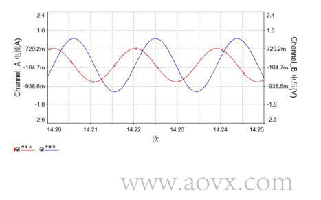
Figure 10-5
One problem: an AC voltage signal V1, after passing through a capacitor, produces a voltage signal Vo. Are the phases of the two voltage signals the same? Is there an offset?
Within the bandwidth (within the cutoff frequency), there is no phase shift, as shown in Figure 10-6. But when it is outside the cutoff frequency, there will be a phase shift, as shown in Figure 10-7.

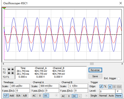
Figure 10-6
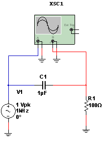
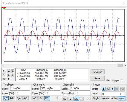
Figure 10-7
AOVX main device included 4 series :
*Goods monitoring
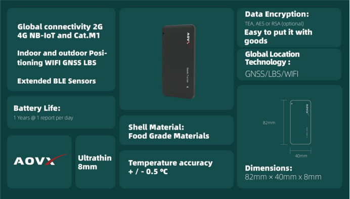
*Assets tracking
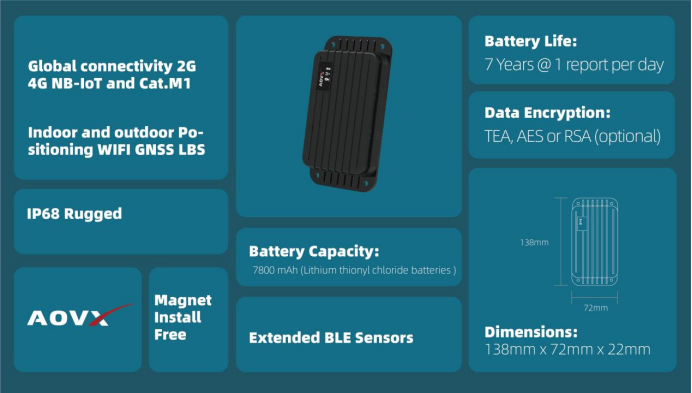
*Vehicle tracking
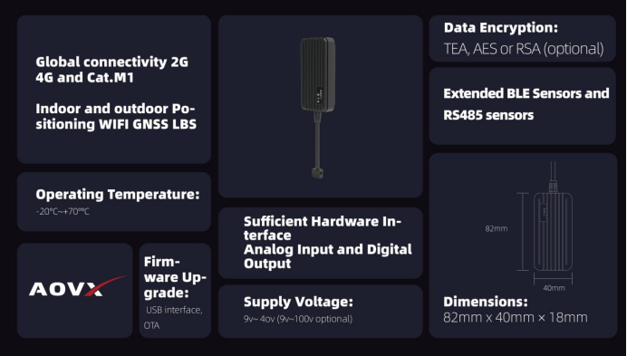
*Environmental monitoring
Website: www.aovx.com
Email: info@aovx.com
Interest in more solutions? follow us at Linkedin:
https://www.linkedin.com/company/aovxassetstracker/mycompany/?viewAsMember=true

Learn more about AOVX :
The wireless sensor monitoring technology developed by the AOVX creatively integrates the three elements of “people”, “goods” and “warehouses” in the logistics supply chain into one platform, and conducts all-around data collection and analysis for personnel, goods, and the environment in warehousing and logistics monitor.


Latest Posts
Categories


