News
In this hardware knowledge workshop, our engineers continued to analyze the triode, which was the topic of the previous week.

The triode plays a very important role in our tracking device, mainly as a switch controlled by the device signal.

For example, during the operation of the cargo tracking device, the main function of the device is to monitor the real-time location, storage environment, movement status and other data of the cargo during transportation. Avoid problems such as loss, exchange, deterioration, serious collision loss and other problems of goods during transportation.

After the device's sensor collects data, the triode completes the operation of transmitting signals from the hardware device to the cloud backend by controlling the device's signal switch.
This issue mainly introduces the characteristics and working status of the triode.Learn the characteristics and working conditions of the triode
Learn the input and output characteristics of triodes
In fact, when we analyze and discuss the triode, the fundamental is to analyze the input and output of the triode, and study the characteristic relationship between the base current as the input and the collector current as the output, as shown in Figure 16-1.
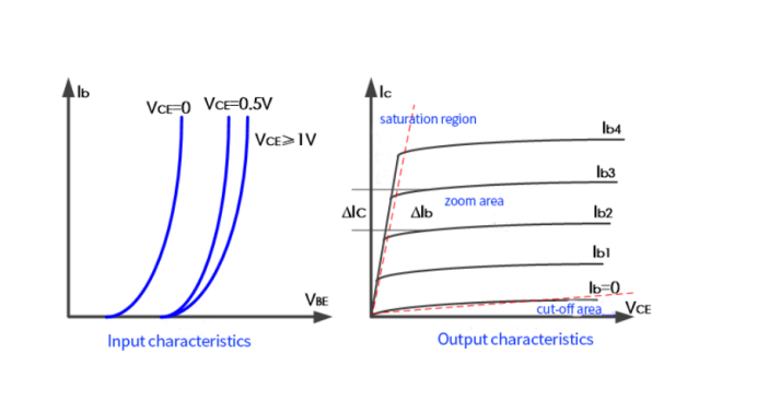
Input characteristics: describe the relationship between the base current L(b) and the emitter junction voltage drop V(be), that is, L(b) is determined by V(be).

In fact, it is the characteristic exponential relationship between the forward current of a PN junction and the applied voltage. Generally, when V(be)>0.7V, there is an obvious base current L(b).
Let's take a look at why V(ce)=constant, because we want to establish an input relationship, then we will make it constant first to affect the relationship. The increase of V(ce) will cause more free electrons from the emitter to be drawn into the collector to increase L(c), thereby reducing the free electrons involved in recombination in the base, which will reduce L(b) . At this time, if you want to keep L(b) unchanged, you need to increase the voltage of V(be), so that more free electrons are injected from the emitter to the base.
By the way, when the voltage of V(ce) is large enough, the free electrons in the emitter region are basically collected to the collector, and the collector current will not increase any more.
Generally, the low-power tube V(ce)=1V can be achieved. We can also see from the input characteristic curve that when V(ce)≧1V, V(be) will not increase, which means that L(c ) will not increase.
Output characteristics: describe the relationship between collector current L(c) and tube voltage drop V(ce).

In the cut-off region, because the input V(be) voltage is too small, the base-emitter junction is not turned on, so that L(b)=0. In this way, even if V(ce) is large, L(c) has almost no current. This also shows that when L(b)=0, L(c) has basically no obvious relationship with V(ce).
In fact, when L(b)=0, L(c) is not really 0, but there is a leakage current related to V(ce).
In the saturation region, the output current L(c) increases rapidly and linearly with the increase of V(ce), and remains basically unchanged with the increase of L(b). Under normal circumstances, the vertical dotted line in the right figure of Figure 16-1 is about 0.3V, that is, after the transistor is saturated, the saturation voltage between the collector and the emitter is V(ces)=0.3V.
In the magnified area, L(b) is a step change of the equidistant relationship, resulting in a set of equidistant parallel lines. This shows that L(c) has nothing to do with V(ce), but directly generates L(c)=β*L(b) relationship with L(b), or the triode in this state is completely driven by the voltage V( be) input, current L(c) output transconductance device, voltage-controlled or current-controlled current source.
Make the triode circuit enter the desired working state
Cut-off: as long as V(be) is not turned on;
Saturation: Let the transistor V(ce) be 0V, so that the collector power supply voltage is divided by the collector resistance to obtain the current L(c). If the set base current L(b) is greater than L(c)/β, then the transistor circuit is the saturated state. When using an ordinary triode, set the base current to L(b)≥0.1*L(c)
When , the triode basically enters the saturation state.
Amplification: When the forward bias of the emitter junction is satisfied, if the base input current is relatively small, the amplification relationship of L(c)=β*L(b) will be satisfied.
Status | Output | |
V(ce) | L(c) | |
deadline | greater than V(be), the collector potential is greater than the base potential |
|
saturation | Less than or equal to V(be), the collector potential is less than or equal to the base potential | ≤β*L(b)
|
enlarge | >V(be),The collector potential is greater than the base potential | =β*L(b) |
Always keep in mind the effect of temperature on triodes
The temperature characteristics of the triode are parameters that our hardware engineers must consider. Problems such as circuit errors and component performance changes caused by temperature changes must be fully considered in the design of electronic products, otherwise irreversible design consequences may occur.
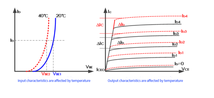
As shown in the left figure of Figure 16-2, the input characteristic curve of the triode shifts under the influence of temperature, which is basically consistent with the temperature characteristic of the diode. This effect is also concluded in the quantitative relationship produced by the E-M equation. When the base current L(b) is constant, V(be) decreases with temperature at a rate of about 2.1mV/°C. Likewise, if V(be) remains constant, L(b) will increase as the temperature increases, and vice versa.
As shown in the right figure of Figure 16-2, in the relationship between the output characteristics of the transistor and the temperature, L(b) of the same bottom mark of the solid line and the dashed line are equal. When the temperature increases, it can be directly seen that the output current L(c) increases, which also shows that the current amplification factor B=L(c)/L(b) is increased under the influence of the increase in temperature.
L(cbo) | L(ceo) | |
Definition | When the emitter is open, the reverse current is generated by the reverse voltage applied to the collector junction. | The penetration current between the collector and the emitter when the base is open. |
Relationship |  | |
Temperature effect | For every 10°C increase in temperature, both currents approximately double, and vice versa. | |
Selection emphasis | The smaller the two currents, the more stable the performance of the tube. Since the collector junction is reverse pressured, the silicon tube is much smaller than the germanium tube for reverse current, so the temperature stability is also better for the silicon tube. | |
Learn more about AOVX :
The wireless sensor monitoring technology developed by the AOVX creatively integrates the three elements of “people”, “goods” and “warehouses” in the logistics supply chain into one platform, and conducts all-around data collection and analysis for personnel, goods, and the environment in warehousing and logistics monitor.
Website: www.aovx.com
Latest Posts
Categories
Tags


