 03 March,2022
 By Aovxers
 AOVX hardware workshop
As one of the most commonly used basic components, the triode is mainly used in aovx equipment to amplify current and control circuits. In the sharing of previous issues, we introduced a lot of knowledge about triodes, which shows the importance of triodes.
As an enterprise specializing in asset monitoring, Aovx has achieved in-depth cooperation with customers in many industries.

Aovx's products mainly include 4 series. "GAVE"

By showcasing the diverse solutions of these four series of products, we have gained more than 3,000 followers on LinkedIn.
Want to learn more about Aovx solutions?
Please follow our company page : https://www.linkedin.com/company/aovxassetstracker/posts/?feedView=all&viewAsMember=true

Next, follow our hardware engineers and continue to learn another knowledge point of triodes: switching circuits
switch control circuit
The switch control circuit is a very common circuit, and engineers need to understand three issues to correctly implement this circuit:
① The triode works in a saturated state;
②How to choose the base resistance properly;
③ How to choose the collector resistance.
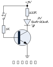
Figure 17-1
The collector resistor selection can be set according to the load current.
In Figure 17-1, we want to drive and light up a light-emitting diode, and the driving current range is 5~20mA. Assuming that we only need 5mA to drive the light-emitting diode, then we need a current of 5mA to flow through the collector of the triode, that is, Lc=5mA. At the same time, after the light-emitting diode is lit, a voltage drop of 2V is generated, and the voltage drop of the triode saturated conduction is 0~0.2V. To continuously output a collector current of 5mA, the maximum value of the collector resistance should be (3V-2V-0.2V)/5mA=160Ω. We choose the collector resistance to be 100Ω within the range, then in the saturated state of the triode, the collector current is 8mA, which can drive and light the LED.
To make the triode work in a saturated state, it can generally be based on the empirical equation of Lb≥0.1*Lc.
Because Lc=5mA.
Lb must be greater than or equal to 0.5mA, so the maximum base resistance is (3V-0.6V)/0.5mA=4.8kΩ, where 0.6V is the junction voltage of the emitter junction of the triode. In the above circuit, it is reasonable for us to take 1kΩ, but the static circuit will be slightly larger, that is, the base current of static turn-on is 2.4mA.
Figure 17-2 shows the application circuit of the triode as the load switch. By controlling the level of the GPIO, it is possible to control whether to supply power to the load.
The relationship between the Vin voltage and the GPIO voltage needs to be considered when choosing a single tube or a dual tube. If the Vin voltage is relatively large, if the single-tube circuit Vin is selected, it will be serially connected to the GPIO through the emitter junction of the transistor Q, which may cause the MCU of the GPIO to be damaged due to overvoltage, so the only way to isolate it is to choose the dual-tube control method. Larger Vin and GPIO.
MOSFETs are usually used instead of triodes in applications, because it is more convenient to use voltage control, and only a small GPIO current is required. That is, PMOS will replace Q1, NMOS will replace Q2, and the resistor R2 will be omitted.
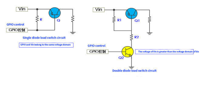
Figure 17-2
Level shift circuit
The level conversion circuits in many system applications use the circuit in Figure 17-3 for unidirectional conversion. Attention should be paid to:
① VA≥V, VB≥V to prevent the BE junction or BC junction of the triode from being turned on to cause the circuit to be connected in series;
② The triode works in two states of cut-off and saturation to form high-level and low-level transmission;
③ Send data on the A side and receive data on the B side.
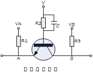
Figure 17-3
In Figure 17-3, when the A terminal is at a low level, the BE junction of the triode is turned on. Since the base current is large enough, the triode is saturated and turned on, and the potential of B is 0.3V higher than that of the A terminal, so that the B terminal also presents a low level. On the contrary, when the A terminal is at a high level, the BE junction of the triode is turned off, and the triode is turned off, then the impedance from the B terminal to the A terminal is very large, and the B terminal is pulled up to the VB by the resistor, thus showing a high level.
A small capacitor connected in parallel with the base resistor, this capacitor is called an accelerating capacitor, and the purpose is to speed up the switching speed of the transistor on and off. Assuming that the circuit does not have an acceleration capacitor for level conversion of the UART circuit, it can only support 115200 baud rate, but after adding this capacitor, it can support 460800 baud rate or even higher.


Latest Posts
Categories


